Shortened,Weighted,Upgraded
Shifter Assembly
Contents
Preface
The goal of this tech note is to supply you with the ability to make your own weighted, shortened shifter and at the same time make it more positive and longer lasting. The Germans were good at what they did but there are just some things that are cost prohibitive in an assembly line. Volkswagen would have made their shifters like this if there weren’t pressure to make the best car that they could for the least amount of money. The plastic socket and steel ball are in expensive and easy to assemble.
This upgrade will make the “H” pattern at the shifter smaller from front to back but will not change the width. It will also allow for adjustment of the location of the pattern. Meaning that you will be able to move the “H” forward or backward relative to your seating position to maximize your comfort.
Supplies
2-Heim joints
1.25” round steel, 4 7/8” long
3/8”x24x1.5” grade 8 bolts
3/8”x24x1” grade 8 bolts
3/8”x24 grade 8 aircraft nuts
3/8” washers
1”x3/8”x2” flat steel stock
Tools
Drill
3/8” drill bit
Welder or access to someone who can do this for you.
Files
Paint
13 mm wrench
7/16” wrench
Pliers
Procedure
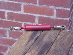
Please refer to picture #1 for the names of the individual parts.
Disassembly: I used a spare shifter that I had lying around. You will probably have to disassemble the shifter from your car. Place the car in neutral and remember to use jack stands and wheel chocks when you have to go under the car. A 13 mm wrench and a pair of needle nose pliers are what you will have to take along under the car with you. I’d also take a rag, as this area of most cars is messy. Remove the relay shaft, the rod, and the selector shaft.
Bench work: Take two nuts and drill the threads out of them with your 3/8” drill. These will become spacer bushings to hold the Heim joints off of the relay shaft and the selector shaft.
Selector shaft: Remove the bushing from the selector shaft. Bolt a drilled out nut to the ball socket side of the selector shaft where the rod was removed. Make sure it is centered in the hole, as the hole is too large for the bolt. Now weld the nut and the bushing to the selector shaft. You are now done with the selector shaft so put it aside.
Relay shaft: Remove the bushing from the relay shaft. Weld your flat stock to the side of the arm that the shaft is on to make it 1 ½” longer. Mark out a 3/8”x 1” slot. Drill as much material as you can out of this area. File out the rest. Test fit a bolt through this slot and make sure it will fit everywhere in the slot. You are now done with the relay shaft and can put it aside.
Rod: Weld a 3/8”x1.5” bolt onto each end of the 1.25” x 4 7/8” round steel rod.
Clean up your welds and give everything a coat of paint or powder coat and you are done with the bench work.
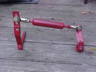
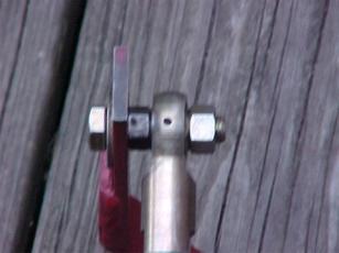
Assembly: (another view) The transmission should still be in neutral. If you are not sure, put the selector rod on the transmission and move it from side to side. You should be able to feel the neutral gate. When the transmission is in neutral the selector rod should be installed in a vertical position. Install the relay shaft and the lever making sure that the ball end of the lever is in the selector lever. Install a nut to each end of the new rod followed by the Heim joints. Make sure there is room for the joint to move. This picture is an assembly that will bind. This picture is of a correct assembly. Adjust the Heim joints so that the centers are approximately 10.5” from each other but do not tighten the lock nuts at this time. Bolt the rod to the selector shaft. Bolt the other end of the rod to the relay shaft slot using the other drilled out nut as a spacer between the slot and the Heim joint.
Adjustment: The slot in the relay shaft is what
allows the “H” pattern to become smaller (vertically). The farther away from
the axle of the relay shaft the Heim joint is, the smaller the pattern will be.
Adjust this to your preference; some trial and error is required here. The
total length of the rod is what determines the location of the “H” pattern for
ergonomic placement. The shorter the rod the farther away from you the pattern
will be and visa versa. Again trial and error is necessary.
Questions? Mail me
Pictures